Introduction to SCCR

In industrial and machine-control systems, the Short-Circuit Current Rating (SCCR) defines how much fault current a control panel (or component) can safely endure without catastrophic failure. If available fault current at the installation point exceeds the SCCR, components can rupture, arcs can ignite, and people and equipment are at risk.
Engineers should design for the absolute worst case, but also the highest fault currents that could exist over time (e.g., service upgrades or plant expansions). SCCR is the safety margin that protects you on that worst day.
Key Terms
- Available Fault Current: The prospective short-circuit current at the panel’s supply terminals if a fault occurs (to ground or between phases). In figure 1, available fault current is denoted by Maximum Possible Peak Current.
- SCCR (Short-Circuit Current Rating): An equipment rating: the maximum fault current a component or assembled panel can withstand for a defined test duration without unacceptable damage.
- Interrupting Rating (IR): For fuses and breakers: the maximum fault current the device can safely interrupt under specified conditions. (IR is not the same as SCCR.)
- Coordination / Let-Through Energy: A device might interrupt a high fault, but the energy let through (I²t/peak) can still damage downstream parts if not coordinated. In figure 1, peak-let through current is denoted by Peak Let-Thru.
Why It Matters
During a short circuit, fault current follows all available return paths, dividing according to their impedances. If any device in those paths can’t withstand the stress, you risk cascading failures, arc-flash hazards, and extended downtime. Designing with SCCR in mind ensures the enclosure and internals remain intact long enough for upstream protection to clear the event.
Mini-Example
Starting from the load side, Branch 1 is protected by an MCCB with 10 kA SCCR and Branch 2 by an MCCB with 15 kA SCCR. Because Branch 1 is the lowest of the two, the assembly is limited to ≤ 10 kA SCCR at this stage.
Upstream, the fusible switch currently uses RK5 fuses. In figure 2, the RK5 let-through downstream of the switch is 21 kA, which exceeds multiple downstream component ratings. The power distribution block (PDB) is 10 kA SCCR, so as configured the system is not acceptable.
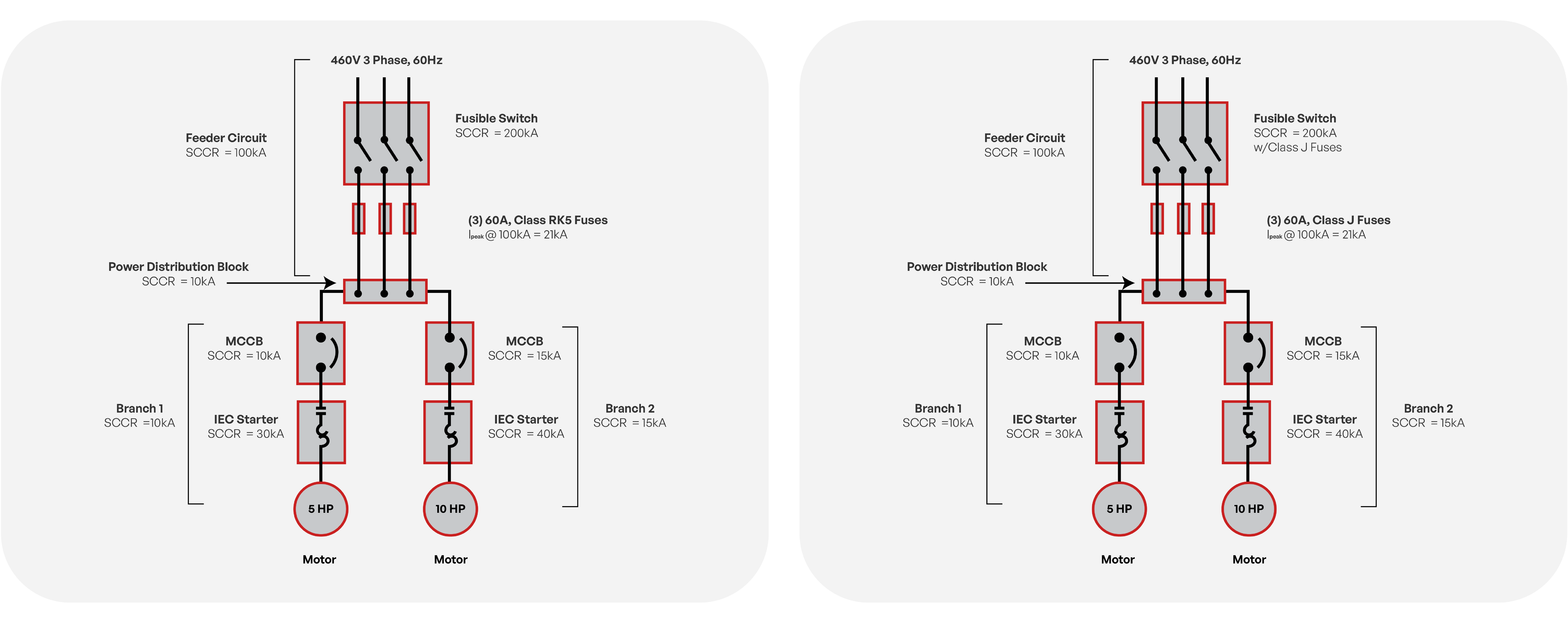
Mitigation: Replace the RK5 with a Class J fuse (properly sized). Class J’s current-limiting performance reduces the let-through to ≈ 10 kA, so downstream devices experience ≤ 10 kA during a fault. With that limitation:
- The 10 kA PDB is protected within its SCCR.
- Branch 1 (10 kA) and Branch 2 (15 kA) are both within their SCCR.
Result: The panel can be assigned 10 kA SCCR (governed by Branch 1), and the assembly becomes compliant once the feeder fuses are upgraded to Class J and properly coordinated.
Key Takeaways
- SCCR defines how much fault energy your system can safely withstand.
- It must always be ≥ available fault current at the install location.
- Current-limiting protection is the practical lever to raise effective SCCR.
SCCR isn’t about nominal operation, instead, it’s about the worst minute your system may ever face. Build in margin and coordinate protection. If you need a high-performance feeder fuse to help elevate SCCR, consider a current-limiting UL 248 Class J option like OptiFuse T6J. See our full Fuse Selection Guide for complete context.
Sebastian Castañeda is a circuit protection specialist and technical writer with application-focused experience in technical support and custom protection design. He contributes practical, application-driven insights to the OptiFuse Blog.