Selective Coordination in Electrical Systems: Time-Current Curves and Fuse Selection

A short circuit on one branch circuit should not take down an entire system.
That is the basic idea behind selective coordination. In practical terms, it means the overcurrent protective device closest to the fault clears first, while upstream devices stay closed so the rest of the system keeps running.
In the NEC’s definition, selective coordination is about limiting an outage to the affected circuit or equipment for the full range of available overcurrents, from overload through available fault current.
It sounds simple enough, but it becomes a serious design issue once you are dealing with emergency power, legally required standby systems, healthcare facilities, and industrial equipment where downtime can cost thousands of dollars.
How Coordination Between Overcurrent Protective Devices Is Verified
Selective coordination is not determined by looking at two device amp ratings and assuming the smaller one will open first. In practice, engineers verify coordination by comparing the upstream and downstream protective devices on a time-current curve.
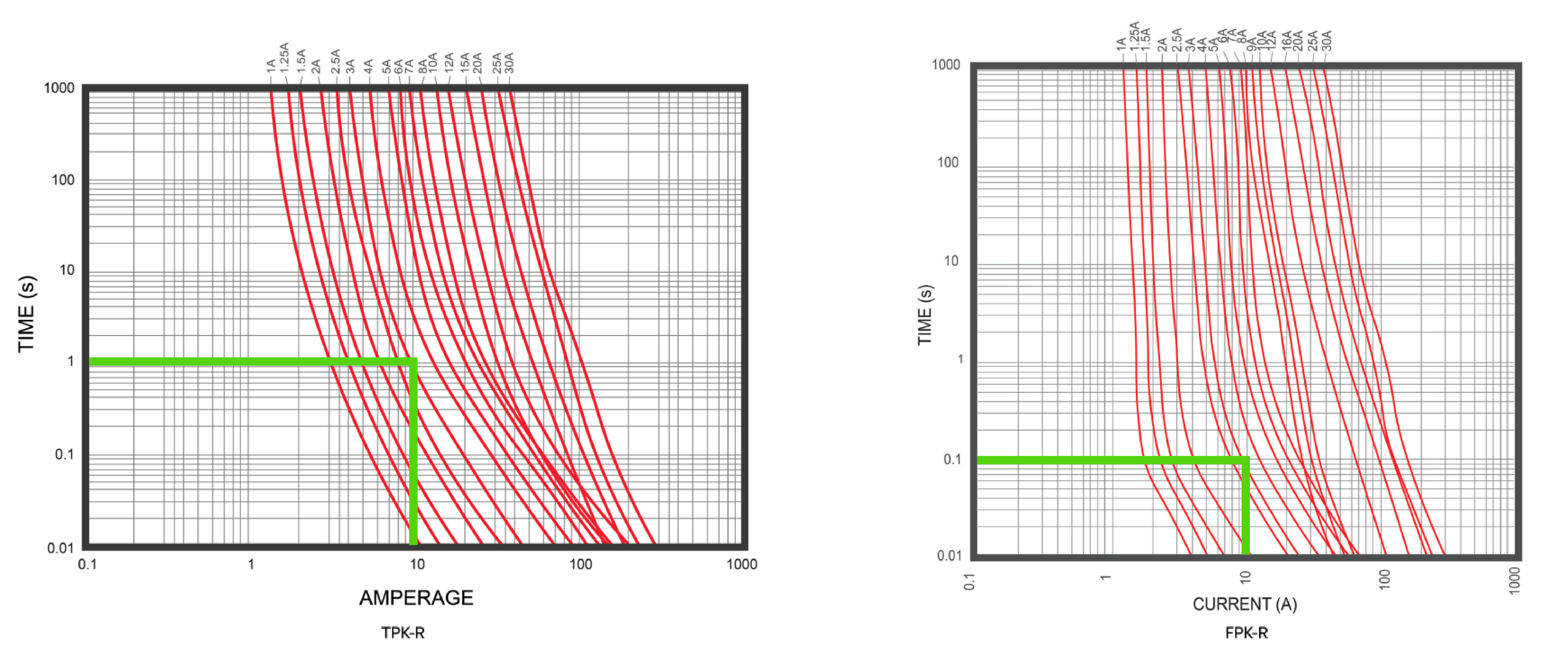
Comparing the 3A curves of OptiFuse’s TPK-R and FPK-R shows how fuse series can behave very differently at the same fault current. At 10A, the TPK-R-3A opens in about 1 second, while the FPK-R-3A opens in roughly 0.1 to 0.2 seconds. This is exactly why coordination cannot be assumed from amp ratings alone.
How Time-Current Curves Are Interpreted
The horizontal axis shows current in amperes, and the vertical axis shows opening time in seconds. If the downstream device clears before the upstream device across the expected range of overcurrent, you are on the right track. If the curves overlap in a meaningful part of the fault range, coordination may be lost.
Overcurrent Conditions Included in Coordination Studies
Time-current curves are especially important because coordination has to hold across more than one type of event. It is not just about large bolted faults. It also includes:
- Overloads
- Mid-range fault currents
- Transformer inrush
- Motor starting current
- The actual available fault current at the point of installation/connection
That is why coordination studies often include not only protective-device curves, but also transformer damage curves, conductor damage curves, and inrush points.
Role of Fuse Systems in Selective Coordination
Fuse systems are often easier to coordinate when the proper current-limiting fuse families are used.
With modern current-limiting fuses, coordination can often be achieved using published selectivity ratios and time-current data, rather than relying only on assumptions from nameplate ratings.
Where OptiFuse Fits In
Industrial fuse selection plays an important role in achieving selective coordination in electrical systems. Engineers rely on available time-current data and fuse characteristics to evaluate how different fuse families behave under overload and fault conditions.
OptiFuse provides industrial fuse families commonly used in coordination-sensitive designs, including current-limiting Class CC (FPK / TPK), Class J (T6J), and Class T (F3T / F6T) products. Each fuse class offers different performance characteristics in terms of time delay, current limitation, and interrupting capacity, which can be evaluated during coordination studies.
For example, Class J time-delay fuses such as the T6J series provide published time-current curves and let-through data that can be used when comparing upstream and downstream device behavior. Class CC fuses are often used in branch circuit applications where compact size and current limitation are key considerations, while Class T fuses are commonly applied in feeder and service entrance protection where high interrupting ratings are required.
In selective coordination studies, this type of published performance data allows engineers to compare device behavior using consistent technical criteria rather than relying solely on nameplate ratings. This supports more predictable coordination analysis when evaluating system protection strategies.
Selective Coordination Ratios Between Class J and Class T Fuses

Selective coordination ratios provide a quick starting point for matching upstream and downstream fuses. In this table, a 2:1 ratio means the line-side fuse should be at least twice the amp rating of the load-side fuse, while a 3:1 ratio means it should be at least three times the amp rating.
These ratios help designers quickly identify Class J and Class T fuse combinations that are more likely to isolate a fault at the load side without opening the upstream device.
Final coordination should still be verified against time-current curves, available fault current, and the specific application requirements. See our Fuse Selection Guide for complete context.
For application support or fuse selection help, contact OptiFuse at [email protected]
Sebastian Castañeda is a circuit protection specialist and technical writer with application-focused experience in technical support and custom protection design. He contributes practical, application-driven insights to the OptiFuse Blog.